Control system based on IrEL Master controller
The control system based on the IrEL Master controller is designed to control the irrigation of medium to large-sized objects – cottage villages, housing complexes, agricultural enterprises.
Along with irrigation control, the system can be used to control technological processes in the landscape or agricultural industries, for example, control of equipment for artificial reservoirs, storage tanks, pump rooms, fertigation, etc., changing the algorithms of the zones depending on the readings of a large set of digital and analog sensors.
It is possible to use the controller as a logger for collecting, storing, processing and transmitting data on various technological processes.
A powerful controller transformer allows for simultaneous irrigation of up to five zones, which, together with the ability to set a separate irrigation time for each zone, allows for the efficient use of the pumping station capacity and fits into power outage schedules.
The use of remote valve controllers based on the RS-485 serial interface significantly reduces the total number of cables in the system. Saving events to files on a microSD memory card and sending event messages in SMS messages provides opportunities for analysis and rapid response. Remote access to the system via the Internet allows centralizing the management of various objects and processes, and monitoring them remotely.
Structural diagram of the system
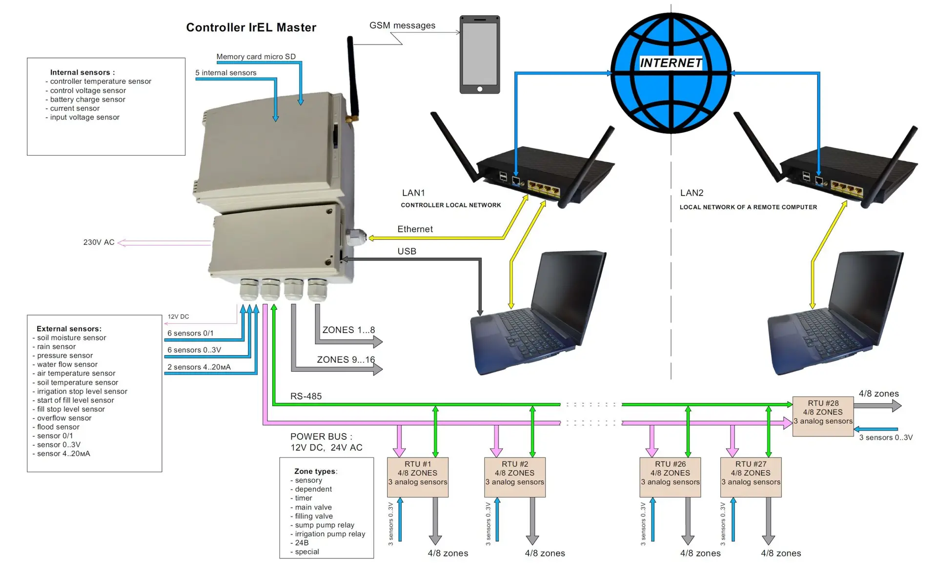
The main component of the system based on the IrEL Master controller is the CPU – a central processing unit located on the central processor board. The CPU controls the operation of the entire system using software and parameters recorded in the memory of the central processor, as well as signals from various sensors arriving at the system inputs. During program execution and based on the results of sensor signal analysis, the CPU controls the switching on/off of actuators by supplying/disabling 24V alternating voltage to zone outputs (zones), recording events on the MicroSD memory card, and generating and transmitting SMS messages. Reading, changing and recording system parameters and zone operation algorithms to/from the CPU or computer, monitoring sensor states, reading events from the memory card and recording these events in the computer memory, updating the CPU software, issuing manual zone control commands, setting the Controller’s communication parameters with local or remote computers is carried out using the Irrigation Manager program, which is installed on the computer and runs under the 64-bit Windows operating system. The computer can be connected to the Controller using such connection types as USB or Ethernet. When using the Ethernet connection type, the computer can be either in the same local network to which the Controller is connected, or in a remote local network (remote computer). The remote computer communicates with the Controller via the Internet. Only one Irrigation Manager can be connected to one irrigation controller at a time.
The upper compartment of the controller case – the printed circuit board compartment – contains the Transformer Board, the Supply Board, two Valves Boards, the CPU Board, the GSM board and the GSM antenna.
The lower compartment of the case – the terminal compartment – contains the reset button and connectors for connecting zones, sensors, power supply for sensors and an external line, USB, RS-485.
The Mother Board occupies both compartments of the controller case and provides communication between the boards and components of the terminal compartment.
The central processor board contains the CPU, microSD memory card, RJ-45 connector for connecting the Ethernet cable, power battery, Wi-Fi module.
The transformer board supplies the system with alternating voltage of 24V AC (with a maximum current of 2.5A). The transformer power allows simultaneous operation of up to 5 zones.
The power board supplies the system with constant voltages of 12V DC (with a maximum current of 1.5A) and 5V DC. In addition, the power board provides the CPU with information about the supply voltage and current consumed by the system through the corresponding sensors, and also allows the CPU to control the supply of alternating voltage of 24V AC to the external line.
The GSM board under CPU control generates SMS messages, the list of which is specified by the user through the Irrigation Manager.
The valve boards control 16 zones (one valve board can control 8 zones) based on CPU commands. Another 48 zones are controlled via RTU (remote terminal units), each of which can control 4 or 8 zones. RTUs can be located at a distance of up to 1200 meters from the Controller. There can be up to 28 RTUs in the system.
The central processor unit communicates with the power board, valve boards and RTUs via the RS-485 interface using the SDI-12 protocol. The data exchange rate is 1200 baud or 1.2 Kbit/sec.
A bus is laid between the Controller and remote RTU devices, which includes a twisted pair cable for transmitting RS-485 interface signals A and B, a DC power supply cable +12V DC/GND and an AC power supply cable 24V AC. There can be several DC and AC voltage sources to reduce the length of the wires.
The controller can process signals from internal, external and remote sensors.
Two internal sensors are located on the power board, three on the central processor board.
External sensors are connected to the controller through the terminal compartment. External sensors include six digital 0/1 type, six analog 0..3V type and two analog 4..20mA type.
Remote sensors are located on the RTU. Each RTU provides for connection of up to three analog 0..3V type sensors.
For each sensor, a sensor type is specified in the Irrigation Manager.
For each zone, a zone type is specified in the Irrigation Manager.
Only sensors of a certain type can influence the operation algorithm of a zone of a certain type.
Zone operation algorithms can be changed by the user.